Cisco IOS XR administrative model

Administrative Model Overview

Cisco IOS XR uses an administrative model based on  task-authorisation rather than privilege levels which involves configuring user-groups and task-groups.

User-groups and task-groups are configured through the AAA command set, authentication commands are used to verify and identify a specific user while authorisation commands are used to verify that an authenticated user has permissions to perform a specific task. Accounting commands are used for logging and recording user or system actions.

AAA data, such as users, users-groups and task-groups can be stored locally, in the router in-memory database and will persist in the configuration file. AAA data can also be stored externally.

Task model

As illustrated in the following figure, users belong to user groups, user-groups get privileges to task-groups, task-groups contain one or more task  IDs.


Task: The operational tasks that enables a user to configure and monitor IOS XR are represented as Tasks IDs.

Task-groups: a set of one or  more Task-IDs.

User-groups: contain one or more users and have privileges to one or more Task-groups. User-groups can be user-defined or predefined. Cisco IOS XR has the following predefined groups:
RP/0/0/CPU0:ios#show aaa usergroup ?
  |              Output Modifiers
  root-lr        Name of the usergroup
  netadmin       Name of the usergroup
  operator       Name of the usergroup
  retrieve       Name of the usergroup
  sysadmin       Name of the usergroup
  maintenance    Name of the usergroup
  root-system    Name of the usergroup
  provisioning   Name of the usergroup
  read-only-tg   Name of the usergroup
  serviceadmin   Name of the usergroup
  cisco-support  Name of the usergroup
Users are classified in the following categories:

Root: users with complete administrative authority.

Root SDR: users with Secure domain router complete administrative authority.

SDR: users with access to a specific Secure domain router.

To show the current logged in user type:
RP/0/0/CPU0:ios#  show user
Wed Sep 25 20:17:03.403 UTC
gngogh
To show the user-group a user belongs to type:
RP/0/0/CPU0:ios#show user group 
Wed Sep 25 20:26:39.453 UTC
root-system
To show user allowed task IDs type:
RP/0/0/CPU0:ios#show user tasks 
Wed Sep 25 20:29:11.033 UTC
Task:                  aaa  : READ    WRITE    EXECUTE    DEBUG
Task:                  acl  : READ    WRITE    EXECUTE    DEBUG
...
...
...
The command "show aaa usedb [user-name]" will display the user group and related task IDs

Configure Users, User-groups and Task-groups.

configure a task-group
RP/0/0/CPU0:ios(config)#taskgroup monitors
RP/0/0/CPU0:ios(config-tg)#task read network
configure a user-group
RP/0/0/CPU0:ios(config)#usergroup monitors
RP/0/0/CPU0:ios(config-ug)#taskgroup monitors
configure a local user
RP/0/0/CPU0:ios(config)#username monitor
RP/0/0/CPU0:ios(config-un)#password cisco.123
RP/0/0/CPU0:ios(config-un)#group monitors

ATM protocol

Architecture Overview

Asynchronous Transport Mode protocol is designed to transport data with guarantees for QOS in which information is organised into small, fixed-length packets, called cells. Due to this nature ATM switches can perform cell switching in hardware improving speed and efficiency.

ATM functionality corresponds to the physical and part of the data-link layers of the OSI model. ATM supported functionality is often described as a three-dimensional reference model that is composed of layers and planes.


The ATM reference model is composed of the following ATM layers:

Physical Layer is responsible for synchronising transmission and reception by sending and receiving a continuous flow of bits with associated timing information. This layer corresponds to the OSI physical layer.

ATM Layer is responsible for the simultaneous sharing of virtual circuits over the physical link and passing cells through the ATM network. To do this, it uses the VPI and VCI information in the header of each ATM cell. Combined with the ATM adaptation layer, the ATM layer corresponds to the data-link layer of the OSI model.

ATM adaptation Layer is responsible for isolating higher layer protocols from the ATM process. The AAL prepares data into payloads.

The ATM reference model is composed of the following planes:

Control plane is responsible for managing signal requests.

User plane is responsible for managing data transfer

Management plane is divided into two sub-planes:

  • Layer management control specific layer functions, such as detection of failures and protocol problems.
  • Plane management manages and coordinates functions related to the complete system. 

Protocols in the ATM layers provide communications between ATM switches while the protocols in the ATM adaption layer provide end-to-end user communications. Interfaces between users and network equipment are called UNI (user network interface), interfaces between ATM switches are called NNI (network-network-interfaces).


ATM Packets (cells)

ATM cells are 53 bytes in length where the first 5 bytes are used for header information and the last 48 bytes are used for payload information.


The difference between the two types of ATM cells is that the cells at the user-network interface carry a data field for the flow control of data from users. This means that only eight bits are available for virtual path identifiers, rather than 12 bits at the network-node interface.

ATM networks identify virtual connections using a combination of Virtual path identifiers and Virtual channel identifiers, this type of combination provide hierarchy in the numbering of virtual connections, by which a virtual path contains a number of virtual channels.

The number of virtual connections available between a user and network interface is less than between network interfaces, due to the fact that user-network interface cells have less 4 bits available for  virtual connections.

The payload type field is used to identify the type of ATM cells. The Cell Loss Priority (CLP) field is used to provide guidance to the network in the event of congestion. A value of 0 indicates a cell of relatively higher priority, which should not be discarded unless no other alternative is available. The header error control field contains a cyclic redundancy check on the other bytes in the header.

Packet over Sonet

SONET/SDH Overview

Synchronous optical network and synchronous digital hierarchy are transport technologies that are used to transmit synchronously large amount of data across relatively long distances using fibre optics links that form the backbone of communication networks. For shorter distances SONET can use copper links. SONET is used in America and SDH is used everywhere else in the world.

The frame format used by SONET is the synchronous transport signal with a base level signal of STS-1 at 51.84 Mbps. The frame format used by SDH is synchronous transport module with a base level signal of STM-1 at 155.52 Mbps.

SONET/SDH rate multiplier is 4 and every higher bandwidth connection is 4 times faster than the one before with a bandwidth limit of up to 40Gbps.

SONET basic transmission frame is STS-1, consisting of 9 rows by 90 columns with the total size of 810 bytes. A single SONET  STS-1 frame is transmitted in 125µs or 8000 frames per second. 8000 fps * 810 B/frame = 51.84 Mbps. SONET frame includes various overhead bytes ( 3 bytes/row ) and an envelope capacity for transporting payloads.

SDH basic transmission frame is STM-1, consisting of 9 rows by 270 columns with a total size of 2430 bytes. STM-1 frames are also transmitted in 125µs or 8000 frames per second. 8000 * 2430B/frame = 155.52 Mbps. As with SONET, SDH frames also have various overhead bytes ( 9 bytes/row) and 261 bytes for information payload.

Transport Hierarchy

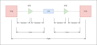
SONET standard includes for functional layers, photonic, path, line and section, SONET layers correspond to the physical and data-link layers of the OSI Model.

Path: 
At this layer the payload is mapped and de-mapped into SONET frames. It is where path terminating equipment interfaces with non-SONET equipment with the SONET network. This layer is responsible for moving the optical signal from source to destination.

Line: 
Line terminating equipment (LTE) originates or terminates one or more sections of the line signal. LTE does the synchronisation and multiplexing of SONET frames. STS multiplexers and Add/Drop multiplexers provide line layer functions.

Section:
A section is a single fibre cable run that can be terminated by any network element (line, path or optical regenerator). Section layer is responsible for formatting SONET frames and convert electrical signals into optical signals. Section Terminating Equipment (STE) can originate, access, modify, or terminate the section header overhead. The first 3 bytes of a STS-1 frame row compromise the section and line overhead.

Photonic:
This layer corresponds to the physical layer of the OSI Model. It includes physical specifications the optical fibre channel.


SONET Network equipment

E-O-E regenerators are used to regenerate signals that travel long distances. The most effective way to regenerate although not necessarily is to convert to the electrical domain and then to the optical domain.

ADM, add-drop multiplexers are the most versatile pieces of SONET networking, as they can add or drop any amount of traffic, ADMs are used to create SONET transport networks consisting of SONET rings and point-to-point connections.

TM, terminal multiplexers are used to aggregate lower-bandwidth traffic into higher-bandwidth SONET pieces for transmission over optical fibres.

SONET Architecture


Configuring POS on Cisco routers

POS interfaces provide data transmission over SONET and SDH frames using cisco HDLC and PPP.

!
interface POS1/0
 ip address 192.168.1.1 255.255.255.254
 encapsulation ppp
 keepalive 5
 crc 32
!

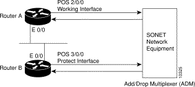
Automatic protection switching is a mechanism used to protect POS interfaces in a SONET network, it works by configuring one interface as the backup for a working POS interface. When the working interface fails the protected (backup) interface quickly assumes its traffic load. This feature is often required when connecting to Telco equipment, such as an ADM multiplexer.

sonet_aps_config.gif 

Router A
router#configure terminal 
router(config)#interface loopback 1 
router(config-if)#ip address 7.7.7.7 255.255.255.0 
router(config)#interface pos 2/0/0 
router(config-if)#aps group 1 
router(config-if)#aps working 1 
router(config-if)#pos ais-shut 
router(config-if)#end 
router#

Router B
router#configure terminal 
router(config)#interface loopback 2 
router(config-if)#ip address 7.7.7.6 255.255.255.0 
router(config)#interface pos 3/0/0 
router(config-if)#aps group 1 
router(config-if)#aps protect 1 7.7.7.7 
router(config-if)#pos ais-shut 
router(config-if)#end 
router#

GRE over IPSEC

As explained in the GRE post, when data needs to be transported between geographically separated locations, GRE establishes a tunnel between end points to allow networks to communicate with each other as if they were directly connected. Since GRE was not built with security in mind, data is sent in clear text and when it has to travel over a third-party network it is susceptible to eavesdropping. This is a security concern that can be easily tackled by adding IPSEC to the mixture, thus preventing eavesdropping and achieving data integrity and confidentiality. 

The GRE over IPSec tunnel has two modes being the tunnel mode the default mode, with tunnel mode the entire GRE packet is encrypted and IPSec will add new IP header. Since GRE and IPSec are using the same tunnel the new IP header added by IPSec will be identical to the IP header added by GRE.

Tunnel mode packet encapsulation:


tunnel mode configuration:
hostname SitE_1R1
crypto isakmp policy 100
 encr 3des
 hash md5
 authentication pre-share
 group 2
crypto isakmp key cisco address 200.10.11.0    
!
!
crypto ipsec transform-set TS esp-3des esp-md5-hmac 
!
crypto ipsec profile ABC
 set transform-set TS
!
interface Tunnel100
 tunnel protection ipsec profile ABC
!
Since IPSec and GRE add overhead to the IP packet, the IP MTU  and the TCP-MSS must be adjusted to prevent packet fragmentation.

IP MTU:
new IP Header
20 bytes
ESP Header (SPI + Sequence)
8 bytes
Init Vector *
8 bytes
New IP Header (GRE)
20 bytes
GRE Header
4 bytes
ESP Pad (ESP-DES/3DES) **
2 bytes
Pad length (ESP Trailer)
1 byte
Next Header (ESP Trailer)
1 byte
ESP-MD5-HMAC (ESP Trailer) ***
12 byte
Total
76 bytes

In this example the IP MTU should be set to 1500 - 76 = 1434

* According to the ESP encryption type, the Init Vector size can be 8 bytes for DES/3DES or 16 bytes for AES.

** ESP Padding varies according to the ESP encryption type, for DES/3DES the size is 2 bytes and for AES the size is 10 bytes.

*** The ESP Trailer varies according to the ESP integrity type, 12 bytes for MD5-HMAC or SHA-HMAC, 16 bytes for SHA-256-HMAC, 24 bytes for SHA-384-HMAC and 32 bytes for SHA-512-HMAC.

TCP-MSS:
TCP Header
20 bytes

The Maximum segment size should be the IP MTU - TCP-MSS, 1434 - 20 = 1414

Transport mode packet encapsulation:


transport mode configuration:
hostname SitE_1R1
crypto isakmp policy 100
 encr 3des
 hash md5
 authentication pre-share
 group 2
crypto isakmp key cisco address 200.10.11.0    
!
!
crypto ipsec transform-set TS esp-3des esp-md5-hmac
 mode transport 
!
crypto ipsec profile ABC
 set transform-set TS
!
interface Tunnel100
 tunnel protection ipsec profile ABC
!
In transport mode since the GRE IP header is not duplicated the overhead is less then tunnel mode.

IP MTU:

new IP Header
20 bytes
ESP Header (SPI + Sequence)
8 bytes
Init Vector *
8 bytes
GRE Header
4 bytes
ESP Pad (ESP-DES/3DES) **
6 bytes
Pad length (ESP Trailer)
1 byte
Next Header (ESP Trailer)
1 byte
ESP-MD5-HMAC (ESP Trailer) ***
12 byte
Total
60 bytes

In this example the IP MTU should be set to 1500 - 60 = 1440

* According to the ESP encryption type, the Init Vector size can be 8 bytes for DES/3DES or 16 bytes for AES.

** ESP Padding varies according to the ESP encryption type, for DES/3DES the size is 6 bytes and for AES the size is 14 bytes.

*** The ESP Trailer varies according to the ESP integrity type, 12 bytes for MD5-HMAC or SHA-HMAC, 16 bytes for SHA-256-HMAC, 24 bytes for SHA-384-HMAC and 32 bytes for SHA-512-HMAC.

TCP-MSS:
TCP Header
20 bytes

The Maximum segment size should be the IP MTU - TCP-MSS, 1440 - 20 = 1420

A good IP MTU Calculator can be found here